


Please click here: https://www.electric-linear-actuators.com/blogs/news-1/how-to-choose-the-suitable-linear-actuator-based-on-the-weight-of-the-trapdoor
If you don't know how to calculate it, please contact us for help.
Video:
Use the Slide Controller With Slide Potentiometer to Control Linear Actuator A2 With Potentiometer
Install an Electric Linear Actuator for the Cellar Door
Install two Electric Linear Actuator for the Cellar Door
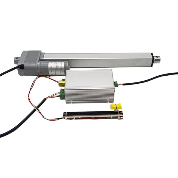
Package Include:
1 x Linear Actuator A2 With Potentiometer
1 x Slide controller
1 x 10K Slide potentiometer
1 x User manual
The information for electric linear actuator:
Feature:
High-quality products and high-quality services
New housing design, high working stability
Metal housing, able to work in very harsh environments
Metal gearbox, high strength wear-resistant gear
Aluminum alloy telescopic tube and outer tube, good corrosion resistant
Heavy duty design, high-power DC motor
Strong thrust, up to 2000N / 200 Kgs / 450 lbs
Multiple speed options, from 5 mm/second to 160 mm/second
Multiple stroke options, from 10 mm to 1000 mm
We can customize any stroke length from 10mm to 1000mm, such as 225mm, 660mm, 950mm and so on.
With a built-in potentiometer
Advanced waterproof and dustproof technology
Low power consumption and low noise
Built-in two limit switches, linear actuator will automatically stop when stroke rod reaches the limit position.
Automatically lock after stopping, and no power supply is required.
Maintenance-free
Specifications:
Optional working voltage: DC 12V or DC 24V. Unless you only have 12V power supply available, we recommend you choose the linear actuator with 24V working voltage.
Stroke range: 40 inches or 1000 mm
Optional speed: 30±5mm/s, 50±10mm/s, 100±15mm/s, 160±20mm/s
The above is the speed at no load, and the actual working speed will gradually slow down as the load increases.
Max Load capacity: 2000N / 200 Kgs / 450 lbs at 5mm/s
Linear actuator can get maximum load capacity when it operates in the vertical direction, and the pulling force is less than pushing force.
No-load current: 0.5~1A at 12V or 0.3~0.5A at 24V
Full load current: 3~6A at 12V or 1.5~3A at 24V
Please use a 12V/6A or 24V/3A power supply to power a linear actuator or use a 12V/10A or 24V/5A power supply to power two linear actuators, or use a 12V/20A or 24V/10A power supply to power four linear actuators.
Shaft diameter: 20mm
Mounting holes diameter: 6mm
Housing material: Aluminum Alloy
Stroke rod material: Aluminum Alloy
Gear material: Steel Alloy
Motor type: Brushed DC Motor
Built-in potentiometer: 10K (You can specify other resistance values)
Duty Cycle: 20%, max 5mins continuous use
Cable: Five-core Cable (Two power wires and three potentiometer output wires)
Certifications: CE
Environment temperature: -26℃ to 85℃
Operating noise: about 46dB~56dB (Linear actuators with different parameters will have different noise levels.)
IP rating: IP65
Operation:
The electric linear actuator has a five-core cable.
1) The red and black lines are two power lines of the electric linear actuator.
Connect the DC power supply to two power wires of the electric linear actuator. When linear actuator is connected to DC power supply, the stroke rod will extend outward; after switching the power in the reverse direction, the stroke rod will retract inward.
The direction of movement of the stroke rod can be changed by switching the polarity of DC power supply.
2) The white, blue and yellow wires are the three output wires of the potentiometer.
The blue and yellow wires are connected to the two terminals of the potentiometer, it is a fixed resistance value.
When the stroke rod is extended outwards, the resistance between the white and blue wires will decrease accordingly, and the resistance between the white and yellow wires will increase accordingly.
When the stroke rod is retracted inward, the resistance between the white and blue wires will increase accordingly, and the resistance between the white and yellow wires will decrease accordingly.
Different speeds and corresponding maximum thrust:
| No-load Speed | Maximum Thrust |
| 5mm/s | 2000N / 200 kg / 450 lbs |
| 10mm/s | 1000N / 100 kg / 200 lbs |
| 15mm/s | 800N / 80 kg / 180 lbs |
| 20mm/s | 700N / 70 kg / 160 lbs |
| 30mm/s | 500N / 50 kg / 110 lbs |
| 50mm/s | 300N / 30 kg / 60 lbs |
| 100mm/s | 150N / 15 kg / 30 lbs |
| 160mm/s | 100N / 10 kg / 20 lbs |
Note:
1. The above data is the maximum load capacity that can be obtained when the linear actuator runs in the vertical direction. If the weight of your equipment (such as a cellar door) is 100kg, and you want to use a linear actuator to open this door, you need to calculate the actual force acting on the linear actuator according to your installation method. This force is usually 2-5 times the weight of the cellar door. If you don't know how to calculate it, please contact us for help.
2. The above is the speed at no load, and the actual working speed will gradually slow down as the load increases. Full load speed is approximately 60-70% of No-load speed.
3. Different speeds correspond to different maximum loads. Please select the right speed according to the speed and maximum load you need.
4. Linear actuators are not recommended for continuous operation under maximum load, we recommend letting it work at about half of the maximum load to get a longer working life.
5. For linear actuators with a stroke greater than 500MM, you should not normally allow them to operate at their maximum stroke under heavy loads. If the actual stroke you want is 600MM, we recommend that you choose a linear actuator with a stroke of 700-800MM.
6. The maximum pull force of the linear actuator is slightly less than its maximum thrust force.
7. When the speed of the linear actuator is 100mm/s or 160mm/s, the self-locking force is much smaller than the thrust. At other speeds the self-locking force is greater than the thrust.
The information for slide controller with slide potentiometer :
Feature:
Model: 0043090
Operating Voltage: 12V DC, please use a power supply of 12V5A or more to power it.
Output Voltage: 12V DC
Rated current: 10A
Size of controller: 113 x 88 x 39 mm (4.5 x 3.5 x 1.5 inches)
With a stroke control knob switch and a learning button
With an externally connected 10K Slide potentiometer
Multiple speed options: 5mm/s, 10mm/s, 15mm/s, 20mm/s, 30mm/s, 50mm/s, 100mm/s, 160mm/s
Suitable for linear actuators type A2 with internal potentiometer
The stroke of linear actuator A2 can be controlled by twisting the knob or sliding the slide potentiometer.
Wiring:
If you want to control a 12V DC linear actuator, do as following:
1) Connect the positive pole of DC power supply to terminal <+> of, and connect the negative pole of DC power supply to terminal <->.
2) Connect the five wires of the linear actuator to the controller in the order of black, red, blue, white, and yellow, and you can exchange the black and red wires of the linear actuator to change the moving direction of linear actuator.
3) Connect the three wires of the slide potentiometer to the controller in the order of black, red and white.
How to pair the controller to the linear actuator:
Notice: We have paired the controller to the linear actuator before leaving the factory. No need to re-learn after power off, just learn once.
After connecting the linear actuator, press and hold the learning button first, and then power on the controller. When the linear actuator starts to extend outward, you can release the learning button. When the linear actuator is fully extended, it stops for 2 seconds and then retracts automatically. When the linear actuator is fully retracted, the controller stores the data after waiting for 5 seconds and the pairing is successful.
Operation:
Toggle the toggle switch to the right, which means the linear actuator is controlled by the knob switch.
Toggle the toggle switch to the left, which means the linear actuator is controlled by the slide potentiometer.
1) The operation by the knob switch:
Turn the knob switch to a position in its travel, the linear actuator will extend or retract to the corresponding position in its travel accordingly.
2) The operation by the slide potentiometer:
Slide the handle of the slide potentiometer to a position in its travel, the linear actuator will extend or retract to the corresponding position in its travel accordingly.
When the linear actuator is stopped, the status LED flashes slowly; When the linear actuator is extended or retracted, the status LED flashes rapidly.
Production time:
The linear actuators are the customized products, and these products are not in stock, we need to spend 3~7 working days to produce them according to the specified parameters in your order.
Return or Exchange:
The Linear Actuators are the customized products, we need to produce them according to the specified parameters in your order, so that we do not accept returns or cancel orders. If customers order unsuitable linear actuators themselves, we also do not accept exchanges, please understand.
We can provide 3D CAD model files in STEP format for linear actuators. Please contact us by e-mail if you need them.