


Product Operation Demonstration Video:
How to Pair Remote to Receiver
How to Set Working Mode of Wireless Switch
Package Include:
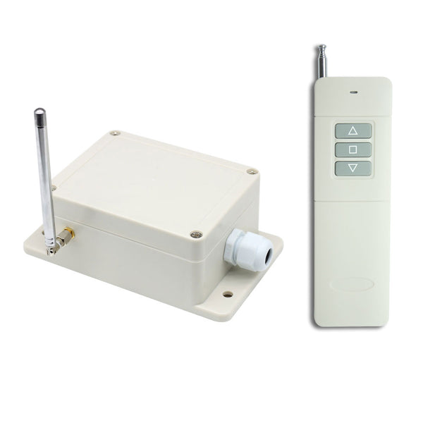
1 x Receiver: S2UW-DC-ANT3
1 x Transmitter: CC-3-2
1 x User manual
Introduction:
This receiver is a super long range remote switch. It is developed by LORA (Long Range) wireless communication technology, so it has ultra-long working distance, ultra-high receiving sensitivity, superior anti-interference ability, and smaller power consumption. It uses a transceiver chip to implement bidirectional communication. Its ideal working distance is up to 5 kilometers, which is an excellent device for remote control and long-distance communication.
Application:
This receiver is an electric device with 2 dry relay outputs, it and the transmitter form a wireless remote-control system. This system can remote control DC motor or linear actuator. If you connect a DC motor to this receiver, you can operate the motor to rotate in positive or reversal direction by using the remote control. If you connect a DC linear actuator to this receiver, you can operate the linear actuator to extend or retract by using the remote control.
Feature:
Wireless control, easy to install.
Suitable for DC motor or linear actuator.
Super long working range: With the transmitter forming a complete set, the maximum working distance may reach 5000 meters in an open area.
Waterproof: The receiver has waterproof case and waterproof connector; it can be installed outdoors.
Four operating voltage versions: DC 6V, 9V, 12V, 24V optional.
Relay Output: This receiver is dry relay output; it can be used to operate both DC and AC equipment. The output terminals are NO / NC (normally open / normally closed), serving as a switch.
You can operate the motor to rotate in positive or reversal direction by using the buttons in the receiver or by the transmitter.
You can operate the linear actuator to extend or retract by using the buttons in the receiver or by the transmitter.
With external antenna, the receiver has a farther working range.
The transmitter / remote can control the receiver from any place within a reliable working distance.
Wireless RF signal from the transmitter can pass through walls, floors, doors, or windows, but it will lose some operating range.
The receiver has reverse voltage protection and overcurrent protection.
The receiver can only be triggered by paired transmitters.
One or more transmitters / remotes can control one or several receivers simultaneously.
Two or more receivers may be used in the same area.
Feedback Function:
The receiver and the transmitter have a Two-way working mode, so the user can know the working status of the receiver by the transmitter.
Two-way working mode: When the receiver is successfully triggered by the signal from the transmitter, it will immediately transmit a feedback signal to the transmitter. When the transmitter receives this signal, it will send out a buzzing sound to inform you that the receiver has been successfully triggered.
Receiver Parameters:
Model: S2UW-DC-ANT3
Operating Voltage: 6VDC (model S2UW-DC06), or 9±1VDC (model S2UW-DC09), or 12±1VDC (model S2UW-DC12), or 24±2VDC (model S2UW-DC24), the operating voltage must be specified when ordering.
Working Frequency: 433.92 MHz
Quiescent Current: ≤6mA
Channel: 2 CH
Output Type: Dry Relays Output (With Normally Open and Normally Closed Terminals)
Maximum Load Voltage of Relay: 240VAC or 28VDC
Maximum Load Current of Relay: 10A / channel
Suitable Wires for Connecting Terminals: 22-12 AWG
Selectable Working Modes: Momentary, Interlocking
Operating Temperature: -20 °C ~ +70 °C
PCB size: 88 x 80 x 18 mm (3.5 x 3.1 x 0.7 inches)
Case size: 153 x 90 x 55 mm (6.0 x 3.6 x 2.2 inches)
Transmitter Parameters:
Model: 0021097 (CC-3-2)
Channel / Button: 3
Button Symbol: ▲ ▇ ▼
Operating Voltage: 9V (1 x 6F22-9V battery, can be used for 12 months)
Working Current: 65mA (when the transmitter is transmitting the signal), 16mA( when the transmitter is receiving the signal).
Standby Current: 5μA
Operating Frequency: 433.92 Mhz
Transmitting Distance: 5000m / 15000ft (theoretically)
Modulation Mode: FSK + LORA
Operating Temperature: -20°C ~ +70°C
Unit Size: 135 x 42 x 25 mm (5.3 x 1.7 x 1.0 inches)
Matching Transmitters:
This receiver only works with 5000m transmitters, such as model CC-3-2 (5000 Meter / 15000 feet range). range).
Super Long Working Range:
The receiver and the transmitter form a wireless remote control switch, the maximum working distance may reach 15000 feet or 5000 meters in an open area.
The maximum working distance is a theoretical data, it shall be operated in an open ground, no barriers, no interference. But in the practice, it will be hindered by trees, walls or other construction, and will be interfered by other wireless signals. Therefore, the actual working distance may not reach this maximum distance.
Usage:
The receiver can be used to to control DC 12V / 24V motor or linear actuator.
Notice: The receiver is dry relay output, not DC/AC power output. Initial state of relay output terminals: Terminals <COM> and <NO> are Normally Open; Terminals <COM> and <NC> are Normally Closed.
Wiring:
If you want to control a DC 12V / 24V motor or linear actuator, do as following:
1) Connect the positive pole of DC power supply to terminal <+>, and connect the negative pole of DC power supply to terminal <->.
2) Connect the positive pole of the DC power supply to the terminal <NO> of two relays, and connect the negative pole of the DC power supply to the terminals <NC> of two relays.
3) Connect two wires of DC motor or linear actuator to the terminal <COM> of two relays, and you can exchange these two wires to change the rotating direction of motor or the moving direction of linear actuator.
Setting different working modes:
The receiver will be set in Interlocking mode before leaving the factory, if you require momentary mode, please follow the following steps.
1) Setting Interlocking mode: Turn on the second bit of the dip switch.
The operation of Interlocking mode with the transmitter CC-3-2:
Press the button ▲ on the transmitter: Motor rotates in positive direction, or linear actuator extends outward.
Press the button ▼ on the transmitter: Motor rotates in reversal direction, or linear actuator inward retracts.
Press the button ■ on the transmitter: Motor or linear actuator stops.
2) Setting Momentary mode: Turn off the second bit and the third bit of the dip switch.
The operation of Momentary mode with the transmitter CC-3-2:
Press and hold the button ▲ on the transmitter: Motor rotates in positive direction, or linear actuator extends outward.
Release the button ▲: Motor or linear actuator stops.
Press and hold the button ▼ on the transmitter: Motor rotates in reversal direction, or linear actuator inward retracts.
Release the button ▼: Motor or linear actuator stops.
How to set the feedback function:
You can turn on the fourth bit of the dip switch to activate the feedback function; or turn off the fourth bit to deactivate the feedback function.
Attention: The first bit of the dip switch needs to be set in the ON position.
How to pair the transmitter to the receiver:
Notice: We have paired the transmitter to the receiver before leaving the factory. If you want to pair more transmitters, please follow the following steps.
1) Press the learning button in the receiver for 1-2 seconds, until the signal LED on the receiver turns on, this indicates that the receiver enters the learning status.
2) Press any one button on the transmitter, if signal LED flashes 3 times quickly and then goes off, this indicates that the pairing is successful.
3) The receiver can learn several transmitters with different codes.
How to delete all transmitters codes stored in the receiver:
We have paired the transmitter to the receiver, if you don’t want the receiver to work with the transmitter, you can delete all transmitters codes stored in the receiver.
Operation: Press and hold the learning button in the receiver for 3-4 seconds, the signal LED first comes on, then flashes 3 times quickly and then goes out, at this time release the learning button, this indicates that all stored codes have been successfully deleted successfully.