


Package Include:
1 x Manual Switch
1 x User Manual
Introduction:
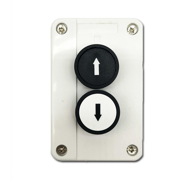
This manual switch has two pushbuttons UP and DOWN. Each button has a set of
normally open contacts. You can connect this manual switch to wired control
terminals of the receiver, or connect to manual switch terminals of linear
actuator synchronization controller, and then use it to control the DC motor
or the linear actuator.
Product Description:
Two buttons: UP, DOWN
Work Mode: Momentary
Button diameter: 30 MM
Hole diameter: 22 MM
Each button is equipped with a set NO contacts
Contact material: silver contacts
Contact rated current: 10A
Operating Temperature: -20°C to +70°C
Waterproof case and waterproof connector
Impact-resistant plastic case
IP rating: IP65
Case size: 105 x 68 x 50 mm (4.1 x 2.7 x 2.0 inches)
Suitable for our receivers with wired control terminals, such as model
S1FC-DC
,
S1PF-DC
,
S1PF3-DC
, S1F2-DC, S1FC-AC, and S1F2-AC.
Suitable for our linear actuator
synchronization controllers
with manual
switch terminals
Wiring:
Connect to the receiver S1FC-DC:
1. Connect the positive pole of DC power supply to terminal <+> of the
receiver's input, and connect the negative pole of DC power supply to
terminal <-> of the receiver's input.
2. Connect the manual switch to the receiver's wired control terminals as
follows:
1) Terminal 3 of UP button to <UP> terminal
2) Terminal 3 of DOWN button to <DOWN> terminal
3) Terminal 4 of both the UP and DOWN buttons to <COM> terminal
3. Connect two wires of the motor or the linear actuator to terminals
<Motor> of the receiver, and you can exchange these two wires to change the
rotating direction of the motor or the moving direction of the linear
actuator.
Connect to the receiver S1PF-DC:
1. Connect the positive pole of DC power supply to terminal <+> of the
receiver's input, and connect the negative pole of DC power supply to
terminal <-> of the receiver's input.
2. Connect the manual switch to the receiver's wired control terminals as
follows:
1) Terminal 3 of UP button to <S1> terminal
2) Terminal 3 of DOWN button to <S2> terminal
3) Terminal 4 of both the UP and DOWN buttons to <GND> terminal
3. Connect two wires of the motor or the linear actuator to terminals
<Motor> of the receiver, and you can exchange these two wires to change the
rotating direction of the motor or the moving direction of the linear
actuator.
Connect to the synchronization controller with manual switch function:
1. Connect the positive pole of DC power supply to the terminal <+> of the
controller, and connect the negative pole of DC power supply to the terminal
<-> of the controller.
2. Connect the manual switch to the controller's manual switch terminals as
follows:
1) Terminal 3 of UP button to <UP> terminal
2) Terminal 3 of DOWN button to <DN> terminal
3) Terminal 4 of both the UP and DOWN buttons to <COM> terminal
3. Plug the linear actuators into into the corresponding channel terminal of
the controller.
Operation:
1) Press and hold the UP button, motor rotates in positive direction, or
linear actuator extends outward; Release the button, motor or linear
actuator stops.
2) Press and hold the DOWN button, motor rotates in reversal direction, or
linear actuator inward retracts; Release the button, motor or linear
actuator stops.