



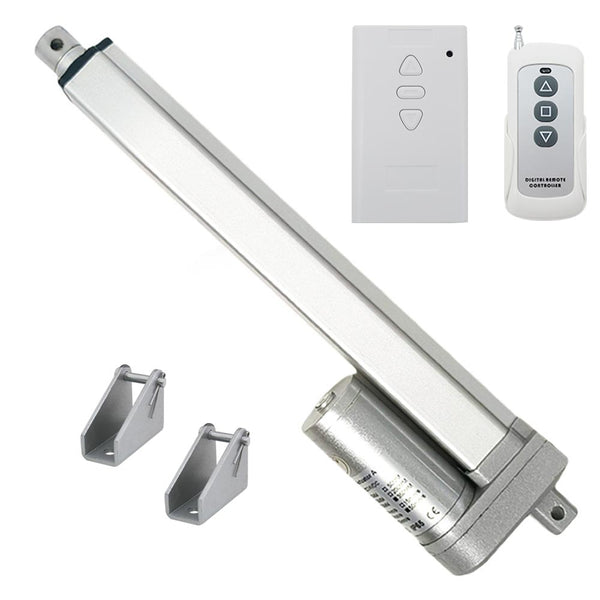
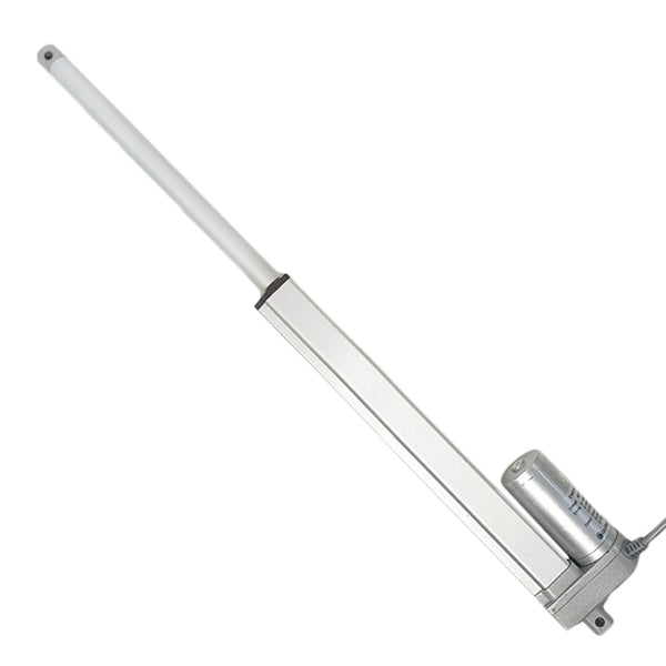


This is a mini industrial linear actuator remote control kit. The entire system delivers a maximum thrust of 2000 N. The remote kit includes a Type A mini industrial actuator, a remote receiver, a CP-3 remote control, and two A-fixing brackets.
If you connect the DC linear actuator to this receiver, you can operate the linear actuator to extend or retract by the remote control.
Application:
Mainly used for doors, windows, cellars, trapdoors, hatchways, solar
tracking system, medical devices, agricultural machinery, vehicles, ships,
elevator platforms, lifting tables, TV lifts, robots, cabinetries, massage
sofas, electric beds, medical chairs, and other electrical equipment. It can
open, close, push, pull, lift, and descend these devices.
It can replace hydraulic and pneumatic products to save power consumption.
The Information for Electric Linear Actuator
The stroke range of linear actuators is 0.4 ~ 60 inches or 10 ~ 1500 mm. We can also customize any stroke length from 10mm to 1500mm, such as 380mm, 750mm, 1250mm and so on.
If you want to view detailed information of linear actuators with different
strokes, such as detailed drawings and dimensional drawings, please click
the following link to view:
Key Features
- High-quality products and high-quality services
- New housing design, high working stability
- Metal housing, able to work in very harsh environments
- Metal gearbox, high strength wear-resistant gear
- Aluminum alloy telescopic tube and outer tube, good corrosion resistant
- Heavy duty design, high-power DC motor
- Strong thrust, up to 2000 N / 200kg / 450lbs
- Multiple speed options, from 5 mm/second to 160 mm/second
- Multiple stroke options, from 10 mm to 1500 mm
- Advanced waterproof and dustproof technology
- Low power consumption and low noise
- Built-in two limit switches, linear actuator will automatically stop when stroke rod reaches the limit position
- Manual override is optional, allowing you to extend or retract the telescopic rod of the linear actuator with hand tools
- The front connector style can be customized: the default is an open hole connector, which can be customized with slotted connector, internal thread connector, etc. And you can provide drawings for customization
- The orientation of the front connector is default; we can rotate it 90 degrees during the production according to the customer's needs
- With auto-locking capability to hold load position after stopping, and no power supply is required
- Maintenance-free
Specifications
| Parameter | Value |
|---|---|
| Working Voltage | DC 12V or DC 24V (24V most commonly used) |
| Stroke Range | 0.4 ~ 60 inches or 10 ~ 1500 mm |
| Optional Speed (No-load) | 5±1mm/s, 10±2mm/s, 15±3mm/s, 20±4mm/s, 25±5mm/s, 40±8mm/s, 55±10mm/s, 65±12mm/s, 100±15mm/s, 160±20mm/s (The actual working speed will gradually slow down as the load increases.) |
| Max Load Capacity | 2000N / 200kg / 450lbs at 5mm/s (Linear actuator can get maximum load capacity when it operates in the vertical direction, and the pulling force is less than pushing force.) |
| No-load Current | 0.5~1A at 12V or 0.3~0.5A at 24V |
| Full Load Current | 3~6A at 12V or 1.5~3A at 24V |
| Recommended Power Supply | 12V/6A or 24V/3A |
| Shaft Diameter | 20mm [0.787 in] |
| Front / Rear Connector Mounting Hole Diameter | 6mm [0.236 in] |
| Housing Material | Aluminum Alloy |
| Stroke Rod Material | Aluminum Alloy |
| Gear Material | Steel Alloy |
| Motor Type | Brushed DC Motor |
| Duty Cycle | 20%, max 5mins continuous use |
| Service Life | approx. 25,000 cycles |
| Power Cable | Ordinary Two-core Wire |
| Linear Actuator Cable Length | 500±10%mm [20 in] (The length can also be customized according to your specific needs) |
| Certifications | CE |
| Environment Temperature | -20℃ to 60℃ |
| Operating Noise | about 46dB~56dB (Linear actuators with different parameters will have different noise levels.) |
| IP Rating | IP65 |
Different Speeds and Corresponding Maximum Thrust
| No-load Speed | Full load Speed | Maximum Thrust | Self-locking Force |
|---|---|---|---|
| 5±1mm/s | 2.5±0.5mm/s | 2000 N / 200 kg / 450 lbs | 2200 N / 220 kg / 490 lbs |
| 10±2mm/s | 5±1mm/s | 1000 N / 100 kg / 200 lbs | 1100 N / 110 kg / 250 lbs |
| 15±3mm/s | 7.5±2mm/s | 800 N / 80 kg / 180 lbs | 900 N / 90 kg / 200 lbs |
| 20±4mm/s | 10±2mm/s | 700 N / 70 kg / 160 lbs | 800 N / 80 kg / 180 lbs |
| 25±5mm/s | 13±2mm/s | 600 N / 60 kg / 130 lbs | 700 N / 70 kg / 160 lbs |
| 40±8mm/s | 20±4mm/s | 300 N / 30 kg / 70 lbs | 350 N / 35 kg / 80 lbs |
| 55±10mm/s | 28±6mm/s | 250 N / 25 kg / 60 lbs | 300 N / 30 kg / 70 lbs |
| 65±12mm/s | 33±6mm/s | 200 N / 20 kg / 50 lbs | 250 N / 25 kg / 60 lbs |
| 100±15mm/s | 50±10mm/s | 150 N / 15 kg / 30 lbs | 100 N / 10 kg / 20 lbs |
| 160±20mm/s | 80±15mm/s | 100 N / 10 kg / 20 lbs | 50 N / 5 kg / 10 lbs |
Note:
1. The above data is the maximum load capacity that can be obtained when the linear actuator runs in the vertical direction. If the weight of your equipment (such as a cellar door) is 100kg, and you want to use a linear actuator to open this door, you need to calculate the actual force acting on the linear actuator according to your installation method. This force is usually 2-5 times the weight of the cellar door. If you don't know how to calculate it, please contact us for help.
2. The above is the speed at no load, and the actual working speed will gradually slow down as the load increases. Full load speed is approximately 60-70% of No-load speed.
3. Different speeds correspond to different maximum loads. Please select the right speed according to the speed and maximum load you need.
4. Linear actuators are not recommended for continuous operation under maximum load, we recommend letting it work at about half of the maximum load to get a longer working life.
5. For linear actuators with a stroke greater than 500MM, you should not normally allow them to operate at their maximum stroke under heavy loads. If the actual stroke you want is 600MM, we recommend that you choose a linear actuator with a stroke of 700-800MM.
6. When the speed of the linear actuator is 100mm/s or 160mm/s, the self-locking force is much smaller than the thrust. At other speeds the self-locking force is greater than the thrust.
7. The maximum pull force of the linear actuator is slightly less than its maximum thrust force.
Installed Length and Stroke Customization
The linear actuator has two built-in limit switches, When the linear
actuator is fully retracted or fully extended, it will stop
automatically.
We can adjust the position of the built-in limit switches during
production to meet customer-specified stroke and retraction lengths.
Example for a linear actuator with a 400 mm stroke:
Retraction Length: 550 mm (center distance between two mounting holes
when the linear actuator is fully retracted)
Extension Length: 950 mm (center distance between two mounting holes
when the linear actuator is fully extended)
Custom Rules:
1) The specified stroke must be less than the standard stroke of the
ordered actuator. For example, a specified stroke of 370 mm is less than
the standard stroke of the ordered actuator (400 mm). In this case, the
retraction length will be reduced by an equivalent value, resulting in a
retraction length of 520 mm. Of course, you can also choose to retain
the original standard retraction length of 550 mm.
2) The specified retraction length must be less than the standard
retraction length of the ordered actuator. For example, a specified
retraction length of 530 mm is less than the standard retraction length
of the ordered actuator (550 mm). In this case, the stroke must also be
reduced by an equivalent value, resulting in an effective stroke of 380
mm.
The Information for Wireless Remote Switch
Application
This receiver is a wireless controller for DC motor or linear actuator, it and the transmitter form a wireless transmitter receiver system. If you connect a DC motor to this receiver, you can operate the motor to rotate in positive or reversal direction by the remote control. If you connect a DC linear actuator to this receiver, you can operate the linear actuator to extend or retract by the remote control. You can connect two limit switches to the receiver and use them to stop the motor or the linear actuator. You also can connect a manual switch to the receiver and use them to control the motor or the linear actuator.
Key Features
- Wireless control, easy to install
- Suitable for DC motor or linear actuator
- DC 9~36V operating voltage range
- Two working modes
- You can operate the motor to rotate in positive or reversal direction by using the buttons in the receiver or by the transmitter
- You can operate the linear actuator to extend or retract by using the buttons in the receiver or by the transmitter
- With three manual buttons: You can control the motor or linear actuator by manual buttons
- With limit control terminals: You can connect sensors, limit switches or external devices to stop the motor or the linear actuator
- With wired control terminals: You can connect manual switches to control the motor or linear actuator
- The transmitter / remote can control the receiver from any place within a reliable working distance
- The wireless RF signal from the transmitter can pass through walls, floors, doors, or windows, but it will lose some operating range
- The receiver has reverse power protection and over current protection built in
- The receiver only works with the selected transmitter which is matched to the receiver
- One or more transmitters / remotes can control one or several receivers simultaneously
- Two or more receivers may be used in the same area
Receiver Specifications
| Parameter | Value |
|---|---|
| Model | S1FC-DC |
| Operating Voltage | 9~36 VDC |
| Output Voltage | 9~36 VDC same as input voltage |
| Working Frequency | 433.92 MHz |
| Channel | 1 CH, can work with 1 DC motor or 1 linear actuator |
| Quiescent Current | ≤6mA |
| Rated Current | 10A, so linear actuator or motor's maximum starting current cannot exceed 10A |
| Wire Range for the Terminals | 22-14 AWG |
| Two Selectable Control Modes | Interlocking mode or Momentary mode |
| Operating Temperature | -20°C ~ +70°C |
| Case Size | 100 x 60 x 30 mm (4.0 x 2.4 x 1.2 inches) |
Remote Control / Transmitter Specifications
| Parameter | Value |
|---|---|
| Model | CP-3 |
| Channel/Button | 3 |
| Button Symbol | ▲■▼ |
| Operating Voltage | 12V (1 x 23A -12V battery, can be used for 12 months) |
| Standby Current | 4uA |
| Operating Current | 14mA |
| Operating Frequency | 433Mhz |
| Transmitting Distance | 500m / 1500ft (theoretically) If you stretches the telescopic antenna, it can have a further working range, which is twice as much as it used to be |
| Modulation Mode | ASK |
| Operating Temperature | -20°C ~ +70°C |
| Unit Size | 92 x 40 x 15 mm (3.6 x 1.6 x 0.6 inches) |
Matching Transmitters
This receiver can work with different transmitters, such as model
CQ-3-2
(50 Meter / 150 feet),
C-2-2
or
C-3-2
(100 Meter / 300 feet),
CP-2
or
CP-3
(500 Meter / 1500 feet),
CV-2-2
(500 Meter / 1500 feet),
CG-3
(500 Meter / 1500 feet) or
CB-3-2
(1000 Meter / 3000 feet).
1) When you set the receiver in Momentary mode, it should work with two
button transmitter, such as model C-2-2, CP-2 or CV-2-2.
2) When you set the receiver in Interlocking mode, it should work with
three or four buttons transmitter, such as model CQ-3-2, C-3-2, CP-3,
CG-3 or CB-3-2.
Working Range
This receiver and different transmitters form a complete set, which can
achieve different working distances. For example, when it and the
transmitter CP-3 form a complete set, the maximum working distance may
reach 500 meters in an open area. When it and the transmitter CB-3-2
form a complete set, the maximum working distance may reach 1000 meters
in an open area.
The maximum working distance is based on theoretical data without
obstacles and any RF interference. In practice, it will be hindered by
trees, walls, or other construction, and will be interfered with by
other wireless signals. Therefore, the actual working distance may not
reach this maximum distance.
The receiver equipped with an external antenna has a larger working
range than the receiver equipped with an internal antenna.
Usage
The receiver can be used to control DC 12V / 24V motor or linear actuator.
Wiring
If you want to control a DC 12V / 24V motor or linear actuator, do as
following:
1) Connect the positive pole of DC power supply to terminal <+> of
Input, and connect the negative pole of DC power supply to terminal <->
of Input.
2) Connect two wires of motor or linear actuator to terminals <Motor>,
and you can exchange these two wires to change the rotating direction of
motor or the moving direction of linear actuator.
Setting Different Working Modes
The receiver will be set in Interlocking mode before leaving the
factory, if you require momentary mode, please follow the following
steps.
Note: Need to restart the receiver after changing the working mode.
1) Setting Interlocking mode: Turn the mode toggle switch in the
receiver to position L.
The operation by the transmitter, such as CP-3:
Press the button ▲ on the transmitter: Motor rotates in positive
direction, or linear actuator extends outward.
Press the button ▼ on the transmitter: Motor rotates in reversal
direction, or linear actuator inward retracts.
Press the button ■ on the transmitter: Motor or linear actuator stops.
The operation by the receiver:
Press the button ▲ on the receiver: Motor rotates in positive direction,
or linear actuator extends outward.
Press the button ▼ on the receiver: Motor rotates in reversal direction,
or linear actuator inward retracts.
Press the button ■ on the receiver: Motor or linear actuator stops.
2) Setting Momentary mode: Turn the mode toggle switch in the receiver
to position M.
The operation by the transmitter, such as CP-3:
Press and hold the button ▲ on the transmitter: Motor rotates in
positive direction, or linear actuator extends outward.
Release the button ▲: Motor or linear actuator stops.
Press and hold the button ▼ on the transmitter: Motor rotates in
reversal direction, or linear actuator inward retracts.
Release the button ▼: Motor or linear actuator stops.
The operation by the receiver:
Press and hold the button ▲ on the receiver: Motor rotates in positive
direction, or linear actuator extends outward.
Release the button ▲: Motor or linear actuator stops.
Press and hold the button ▼ on the receiver: Motor rotates in reversal
direction, or linear actuator inward retracts.
Release the button ▼: Motor or linear actuator stops.
Limit Control Terminals (Limit Switch Function)
The receiver has limit control terminals, and you can connect external
devices (with normally closed contact), such as sensors, limit switches
to limit terminals, then use them to stop the motor or the linear
actuator.
For example, you can connect a normally closed limit switch to terminals
<TOPR> and <COM>, and connect another normally closed limit switch to
terminals <TOPL> and <COM>.
When motor rotates in positive direction, or linear actuator extends
outward, if disconnect two terminals <TOPR> and <COM>, the motor or
linear actuator will stop automatically.
When motor rotates in reversal direction, or linear actuator inward
retracts, if disconnect two terminals <TOPL> and <COM>, the motor or
linear actuator will stop automatically.
Wired Control Terminals (Manual Switch Function)
The receiver has wired control terminals, and you can connect external
devices (with normally open contact), such as manual switches to wired
control terminals, then use them to control the motor or the linear
actuator.
For example, you can connect the manual switch to wired control
terminals <STOP>, <UP>, <COM> and <DOWN> according to the following
wiring diagram.
1) In Interlocking mode: For example, connect 3 pushbutton manual switch
(Model 0040024).
When pressing the UP button, two terminals <UP> and <COM> are connected,
then the motor rotates in the positive direction, or the linear actuator
extends outward. And when pressing the STOP button, two terminals <STOP>
and <COM> are connected, then the motor or linear actuator stops.
When pressing the DOWN button, two terminals <DOWN> and <COM> are
connected, then the motor rotates reversal direction, or the linear
actuator inward retracts. And when pressing the STOP button, two
terminals <STOP> and <COM> are connected, then the motor or linear
actuator stops.
2) In Momentary mode: For example, connect 2 pushbutton manual switch
(Model 0040025).
When pressing and holding the UP button, two terminals <UP> and <COM>
are connected, then the motor rotates in the positive direction, or the
linear actuator extends outward. And when releasing the UP button, two
terminals <UP> and <COM> are disconnected, then the motor or linear
actuator stops.
When pressing and holding the DOWN button, two terminals <DOWN> and
<COM> are connected, then the motor rotates reversal direction, or the
linear actuator inward retracts. And when releasing the DOWN button, two
terminals <DOWN> and <COM> are disconnected, then the motor or linear
actuator stops.
How to Pair the Transmitter to the Receiver
Notice: We have paired the transmitter to the receiver before leaving
the factory. If you want to pair more transmitters, please follow the
following steps.
1) Press the learning button in the receiver for 1- 2 seconds; signal
LED on the receiver turns on, this indicates that the receiver enters
the learning status.
2) Press the button ▲ on the transmitter, signal LED flashes twice; then
press the button ▼ on the transmitter, signal LED flashes twice; then
press the button ■ on the transmitter, signal LED flashes twice; finally
press the learning button in the receiver, signal LED turns off, this
indicates that the pairing is successful.
3) The receiver can learn several transmitters with different codes.
How to Delete all Transmitters Codes Stored in the Receiver
We have paired the transmitter to the receiver, if you don’t want the
receiver to work with the transmitter, you can delete all transmitters
codes stored in the receiver.
Operation: Press and hold the learning button in the receiver for 4-5
seconds until signal LED flashes 3 times and then turns off, this
indicates all stored codes have been deleted successfully.
Accessories
1. Each linear actuator would require two mounting brackets, one to fix
the head of linear actuator and another to fix the bottom of linear
actuator. This kit contains two regular fixed mounting
Brackets A
.
This linear actuator is also compatible with three flat mounting brackets:
Head Fixed Mount Flat Bracket (Model 0043071)
,
Bottom Fixed Mount Flat Bracket (Model 0043072)
and
Fixed Mount Flat Base (Model 0043070)
.
Please buy them from the drop down menu.
2. The front connector style of the linear actuator can be customized: the default is an open hole connector, which can be customized with slotted connector, internal thread connector, etc. And you can provide drawings for customization. If you need customization, please click here to purchase the customized option.
3. Linear actuator fisheye connector can be customized and used in conjunction with the internal thread connector. If you need customization, please click here to purchase the customized option.
4. The orientation of the front connector of the linear actuator is default; we can rotate it 90 degrees during the production according to the customer's needs. If you need to rotate the front connector 90 degrees, please click here to purchase the rotation option.
5. The linear actuator can be equipped with a manual operating device. Even in the event of a power outage, it is possible to extend or retract its telescopic rod using hand tools. If you need a manual operating device to equip the actuator, please click here to purchase it.
6. You need to use a DC24V/3A or DC12V/6A switching power supply to power this kit. This kit does not contain this power supply, please buy it from the drop down menu.
Production Time & Return or Exchange Policy
The linear actuators are customized and not in stock, and we need to spend
3~7 working days to produce them according to the specified parameters in
your order, so that we don't accept returns or cancel orders. If customers
order unsuitable linear actuators themselves, we also do not accept
exchanges, please understand.
We can provide 3D CAD model files in STEP format for linear actuators. Please contact us by e-mail if you need them.
Import Customs Duty Explanation
1. Our store will offer one or two different shipping methods depending on the actual situation of the order. Since we ship from Hong Kong, China to worldwide, import duties will be incurred on the package regardless of which shipping method the customer chooses.
2. For small or lightweight packages, we will select a suitable freight company so that we can pay the import duties on the customer's behalf at the time of shipment. Therefore, the customer will not need to pay any import duties or taxes upon receiving the package.
3. For large or heavy packages, regardless of the freight company we choose, customs will collect import duties and taxes directly from the customer upon customs clearance or upon receipt of the package. The duty amount is usually 20% of the order amount (excluding shipping costs).
4. If the customer wishes us to pay the import duties on the customer's behalf, please contact us when placing the order and pay an additional 20% of the order amount as prepaid duties. We will then pay the duties for the customer.
5. If the customer chooses to pay the import duties themselves, please
contact us after paying the duties and receiving the package. We will
provide the customer with a discount voucher of a certain amount, which
can be used for their next purchase. The discount amount will be the
lesser of the import duties actually paid by the customer and 20% of the
original order amount (excluding shipping costs).
Please note: We cannot refund cash for import duties paid by the customer themselves. Thank you for your understanding.
6. When the transport company or the customs informs the customer to pay the import duties, if the customer doesn't agree to pay, the package will be returned or destroyed, and the customer will need to bear all responsibility and cost.
Click to Download 3D CAD Model Files in STEP format
Product Operation Demonstration Video
Package Include
1 x Electric Linear Actuator A
1 x Receiver: S1FC-DC
1 x Transmitter / Remote: CP-3
2 x Fixing Brackets A
1 x User manual